
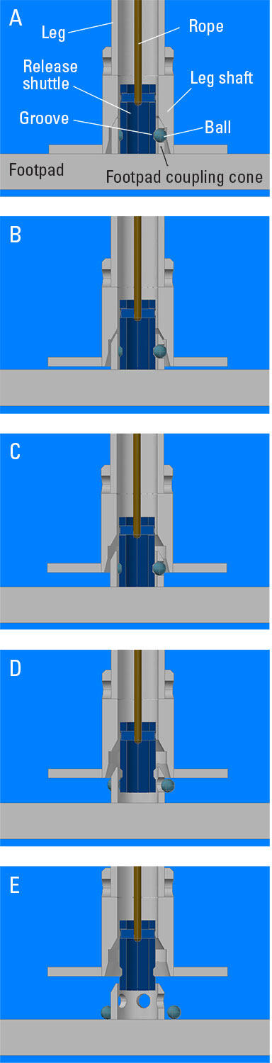
Ball-lock release sequence for releasing tripod leg from footpad
Detailed Description
Ball-lock release sequence for releasing tripod leg from footpad. A, Five stainless-steel balls (greenish blue in this diagram) fit into holes in the footpad coupling cone (gray), which is welded to the footpad. In the locked position, these balls are trapped between the groove in the release shuttle (blue) and the wall of the leg shaft (gray). Tension in the high-strength fiber rope (brown) attached to the release shuttle keeps the footpad coupling cone and attached footpad from separating from the tripod leg. B, An acoustic signal from the surface activates a transponder that releases tension in the rope, allowing the tripod legs to begin to rise via lift provided by the syntactic foam on the upper frame of the tripod. Slack in the rope allows the release shuttle to rest on the footpad while the leg shaft rises. The footpad coupling cone holds the balls in place between the release shuttle groove and the leg shaft as they slide along the interior surface of the leg shaft. C, As the tripod leg continues to rise, the balls reach the level of the enlarged radius at the base of the leg shaft, allowing for sideways movement. D, When there is no more slack in the rope, the release shuttle rises with the leg and the balls are pushed outward by the slanted groove in the shuttle. E, The balls have fallen out of the holes in the footpad coupling cone. Free of the heavy footpads, the tripod will continue rising until it reaches the surface.
Sources/Usage
Public Domain.