Elevation-Derived Hydrography Data Acquisition Specifications: Difference DEM
Elevation-Derived Hydrography Data Acquisition Specifications
Appendix 4. Difference DEM
The DEM used to derive hydrography for the U. S. Geological Survey’s (USGS) 3D Hydrography Program (3DHP) is typically created from multiple lidar data projects. The lidar data, primarily collected by the USGS 3D Elevation Program (3DEP), must meet the USGS Lidar Base Specifications (LBS) that were current at the time of collection. Lidar has been collected as part of 3DEP since 2012, and several revisions to the specifications have been implemented. to the LBS. The technology used to collect airborne terrestrial lidar data has also improved dramatically over time, making positional accuracy, point density, and algorithms for classification of the point clouds considerably different over the years. The DEM difference raster shall document the differences between the source bare-earth DEMs used for deriving hydrography.
The difference raster will be used to identify the location and magnitude where source bare-earth DEMs differ. Because the source bare-earth DEMs are most likely in different coordinate reference systems, there will be slight differences between the rasters throughout the project area. Difference rasters shall be created by subtracting each overlapping source bare-earth DEM from the most recent source bare-earth DEM with a collection area.
- A difference raster for each source bare-earth DEM overlapping the most recent source bare-earth DEM shall be created (Figure 90). Please reference the latest Source Raster and Vector Data Requirements for critical consideration to determine source bare-earth DEM quality.
- The difference raster(s) shall be created by subtracting the overlapping source bare-earth DEM from the source bare-earth DEM determined to be the most recent (Figure 90).
- If the source bare-earth DEMs are in a projection other than EPSG:6350 or EPSG:5703/GEOID18, they shall be transformed to EPSG:6350 and/or EPSG:5703/GEOID18 prior to creating the difference raster.
- The geoid name shall be appended to the VERT_CS[] name field in the spatial reference string. For example: VERT_CS[“NAVD88 height (meter) – GEOID18”].
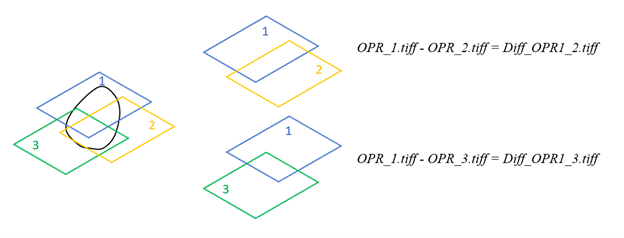
- Naming convention shall follow the example in Figure 91 or Figure 92. All comparisons shall be identified in the raster output name.
- Difference rasters shall be named with the following naming convention: Diff_OPR1_X.tif.
- Diff refers to the product being a difference raster.
- OPR1 is the short name of the most recent source bare-earth DEM.
- X (and so on) is the short name of the source bare-earth DEM overlapping OPR1. See examples below.
- Difference rasters shall be named with the following naming convention: Diff_OPR1_X.tif.
OPR_1.tif – OPR_2.tif = Diff_OPR1_2.tif
OPR_1.tif – OPR_3.tif = Diff_OPR1_3.tif
- A polygon feature class shall be included to indicate Source DEM extents and overlap areas. A simplified name shall be used for each source DEM to identify products being analyzed as difference rasters. See example in Supporting Information.